Material Delivery
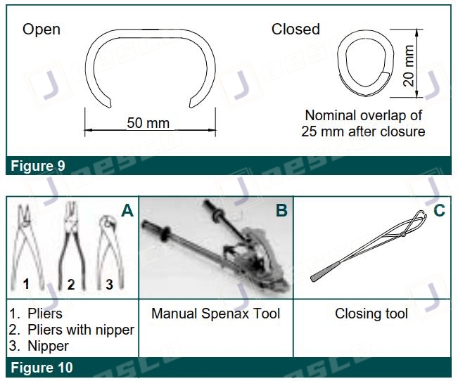
Gabions are manufactured with all components mechanically connected at the production facility. All gabions are supplied in the collapsed form either folded and bundled or rolled. The bundles are compressed and strapped together at the factory for easy shipping and handling. Lacing wire is supplied in coils. Ring fasteners (Figure 9) are shipped in boxes that must be stored in ira dry environment. Preformed braces are shipped in bundles.
Assembly
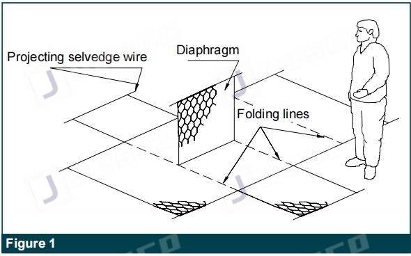
The folded units shall be taken out from the bundle and placed on a hard flat surface. Gabions shall be opened, unfolded pressed out to their original shape. Front, back, and end panels shall be lifted to a vertical position to form an open box and lic(Figure 1).
Panels shall be fastened together with the projecting heavier gauge selvage wire by firmly wrapping the selvage wire around the selvage or edge wire of the intersecting panel or back panel (Figure 2).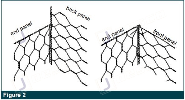
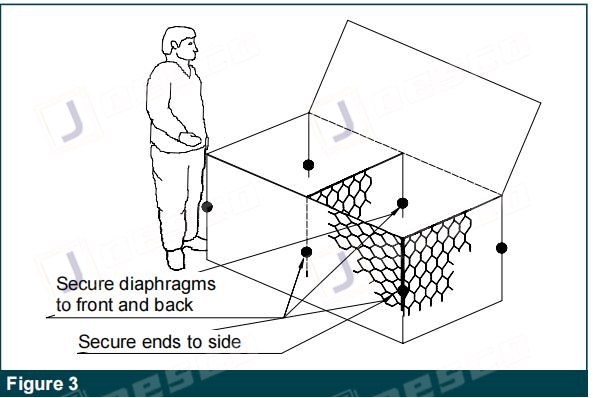
Inner diaphragm panels shall be lifted into a vertical position and secured in the same manner to the front and back of the gabion (Figure 3)
Fixing Procedure
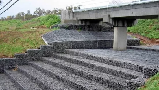
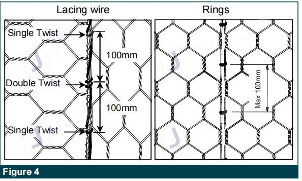
When using lacing wire, cut off a length of wire approximately 1.5 times the length of the edge to be tied. The maximum length of the edge to be tied at one time shall not exceed 1 m. Longeledges shall be joined by several lengths of wire. Lacing wires are secured around the selvage wire or heavier edge wire, where present, by looping and twisting the lacing wire around itself. Proceed tying with alternate double and single loops (Figure 4). Double loops shall be made at intervals not greater than 300 mm. All panels shall be pulled tightly together during the tying operation. Pliers (Figure 10) may be used to create tight The other end of the lacing wire shall be secured by looping and twisting the wire around itself. When using lacing wire to assemble the units, care should be taken to avoid damaging the wire coating. When steel ring fasteners are used, the custom-made Zhengyang Manual Spenax Tool (Figure 10) is required and is available for hire. Rings shall be installed at the top and the bottom connections of the end and center diaphragms and then a maximum spacing of 100 mm along all edges shall be used (Figure 4).
Foundation preparation
The foundation on which the gabions are to be placed shall be level and graded to the elevations as shown on the project drawings, and free of surface irregularities, loose material, and vegetation by the project specifications appropriate measures must be taken for drainage around the foundation, as per the project specifications (geotextile, frameworks, etc.). Geotextiles installed behind gabion structures shall comply with the requirements for subsurface drainage applications.
Installation and Filling
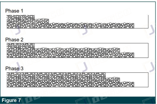
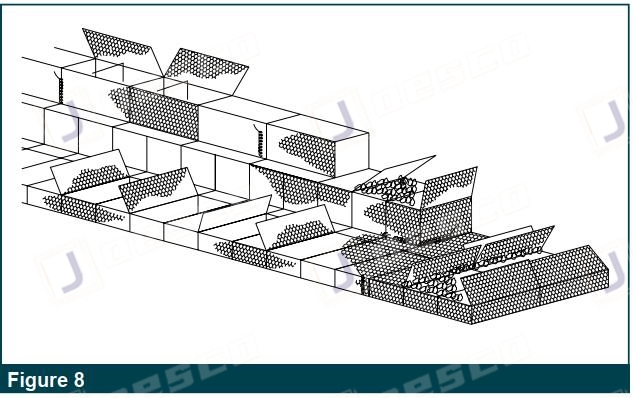
After the foundation has been prepared, the pre-assembled gabions shall be placed in position empty, and tied or fastened adjacent gabion units along all edges to be continuously connected, the monolithic structural unit (Figure Rocks for the gabions may be produced by any suitable quarrying method, and by the use of any device that yields the required sizes within the gradation limits chosen. Rocks shall be hard, angular round, durable, and of such quality that they shall not disintegrate on exposure to water or weathering during the life of the structure. Rocks shall range between 100 mm and 200 mm. The range in sizes may allow for a variation of 5% oversize and/or 5% undersize rock, provided it is not placed on the exposed surface. ln all cases oversize rock shall not be larger than 250 mm, and the undersized rock shall not be smaller than 50 mm. Rock shall be placed in 300 mm lifts for 1 m high gabion units, and 250 mm for for0,5 m high units. The fill layer shall never be more than 300 mm higher than any adjoining cell (Figure 7).
Care shall be taken when placing the stone to ensure that the PVC coating of the wire is not damaged. After a layer of rock has been placed in the cell sufficient hand manipulation of the rock shall be performed to minimize voids and achieve a maximum density of the rock in the gabion. The rock in exposed vertical faces shall be hand-placed to reduce voids in the outer face. Stiffeners or internal cross ties shall be installed connecting the front and back faces of any supported or exposed face at the vertical third points for a 1 m high gabion unit, as the cell is being filled (Figure 5).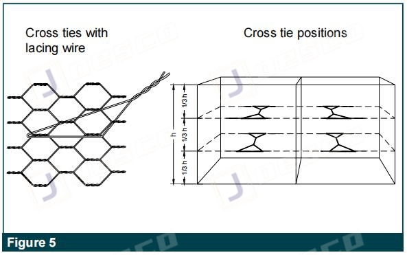
Gabion units installed at the wall ends, having two exposed sides, shall also include a set of cross ties installed perpendicularly to the lateral exposed face. For m-high baskets when used as revetment, stiffeners or internacross connections are not required. When more than one vertical layer of gabions is installed, units shall be overfilled to approximately 25 to 40 mm to allow for natural settlement. The top surface shall be smoothly leveled, minimizing voids. Ensure that diaphragm tops are easily accessible for connecting.
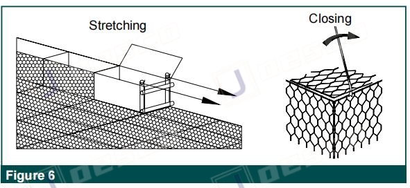
Closing
After the rock has been leveled and the voids minimized, fold the lid down and pull the edges of the panels together. lt should require alight stretching using an appropriate closing tool (Figure 10) or a lid closer to bring the two gabion pieces together. Care shall be taken that the mesh is not deformed or the coating on the wire is damaged. The projecting selvage wire of the lid shall be wrapped in two complete turns around the selvage wire or edge wire on the sides. The lid shall be tightly tied along all edges, ends, and tops of diaphragms. Adjacent lids may be tied or attached simultaneously. All projecting sharp ends of wire shall be turned in on the completed gabion structure.