
Material Delivery
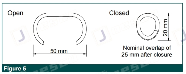
Terramesh System units are supplied in a collapsed form, folded and bundled. The bundles are compressed and strapped together at the factory for easy shipping and handling. Each bundle is labeled with a tag indicating the sizes of the units contained. Lacing wire is supplied in coils. Ring fasteners (Figure 5) are shipped in boxes and should be stored in a dry environment.
Assembly
To assemble the Terramesh System units, follow these steps:
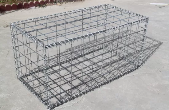
1. Remove the folded units from the bundle and place them on a hard flat surface.
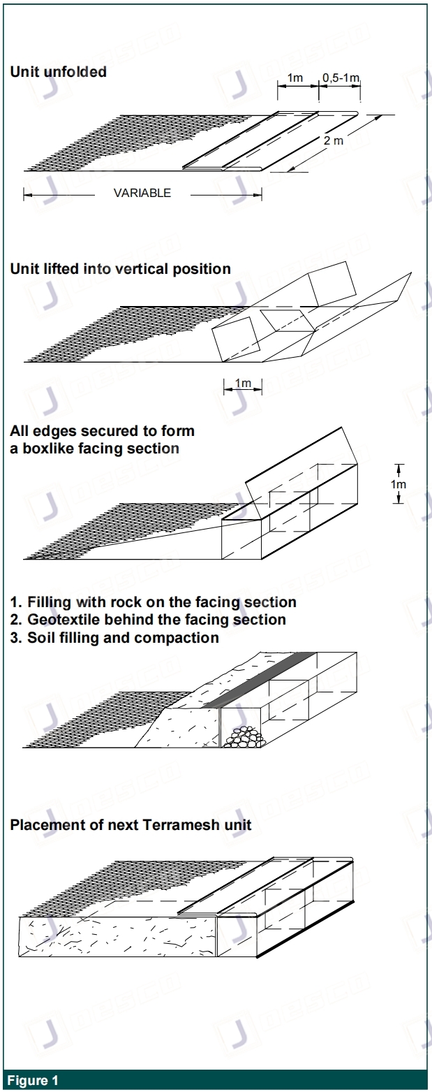
2. Open and unfold the Terramesh System units, pressing them out to their original shape.
3. Lift the front, back, and end panels to a vertical position.
4. Fasten the panels together by firmly wrapping the projecting heavier gauge selvedge wire around the selvedge or edge wire of the intersecting panel or back panel.
5. Lift the inner diaphragm panels into a vertical position and secure them in the same manner.
6. Tie or fasten all edges of the diaphragm and back panels to the front and back of the facing section (Figure 1).
Fixing Procedure
When using lacing wire, follow these steps:
1. Cut off a piece of wire approximately 1.5 times the length of the edge to be tied.
2. The maximum length of the edge to be tied at one time should not exceed 1 meter. For longer edges, join several lengths of wire.
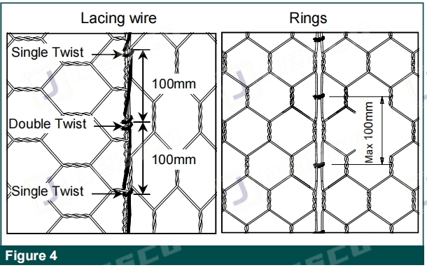
3. Secure the lacing wires around the selvedge wire or heavier edge wire by looping and twisting the lacing wire around itself.
4. Proceed tying with alternate double and single loops (Figure 4). Double loops should be made at intervals not greater than 300 mm.
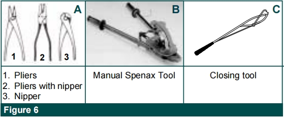
5. Pull all panels tightly together during the tying operation. Pliers (Figure 6) may be used to create tight joints.
6. Secure the other end of the lacing wire by looping and twisting it around itself.
7. When using lacing wire, be careful to avoid damaging the wire coating.
When steel ring fasteners are used, follow these steps:
1. Use the custom-made Maccaferri Manual Spenax Tool (Figure 6), which is required for the installation of ring fasteners. The tool is available for hire.
2. Install rings at the top and bottom connections of the end and center diaphragms, with a maximum spacing of 100 mm along all edges.
3. Connect adjacent units with ring fasteners.
4. Connections made along the panel edges ensure a flat surface for fill placement.
Foundation Preparation
Before placing the Terramesh System units, prepare the foundation as follows:
1. The foundation should be level and graded according to the project construction drawings.
2. The foundation should be free of surface irregularities, loose material, and vegetation, as specified in the project specifications.
3. Take appropriate measures for filtering and drainage of the foundation, such as using filter cloth and drain works.
4. Geotextiles required to be installed behind the units should comply with the requirements for subsurface drainage applications.
Installation, Filling, and Soil Compaction
After the foundation has been prepared, follow these steps:
1. Place the pre-assembled Terramesh System units in position empty and tie or fasten them to adjacent units along all edges to form a continuously connected, monolithic structural unit.
2. Use rocks for the gabion facing section, which may be produced by any suitable quarrying method and within the chosen gradation limits.
3. The rocks should be hard, angular to round, durable, and capable of withstanding exposure to water and weathering.
4. The size of the rocks should range between 100 mm and 200 mm, with a variation allowance of 5% oversize and/or undersize rock.
5. Place rocks in 300 mm lifts for 1 m high Terramesh System units, and 250 mm for 0.5 m high units.
6. The fill layer should not exceed 300 mm higher than any adjoining cell, and care should be taken to avoid damaging the wire coating.
7. After placing a layer of rock in the cell, perform sufficient hand manipulation of the rock to minimize voids and achieve maximum density.
8. Hand place rocks in exposed vertical faces to reduce voids in the outer face.
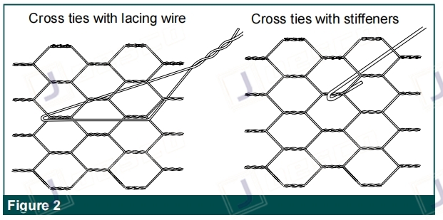
9. Install stiffeners or internal cross ties, connecting the front and back faces of any supported or exposed face at the vertical third points for a 1 m high unit, as the cell is being filled.
10. Overfill the gabion facing section of the Terramesh System by approximately 25 to 40 mm to allow for natural settlement.
11. Smoothly level the top surface, minimizing voids, and ensure easy accessibility of the diaphragm tops for connecting.
Closing
To close the Terramesh System, follow these steps:
1. After leveling the rocks and minimizing voids, fold the lid down and pull the edges of the panels together.
2. Use an appropriate closing tool (Figure 6) or lid closer to lightly stretch and bring the mesh panel pieces together. Take care not to deform the mesh or damage the wire coating.
3. Wrap the projecting selvedge wire of the lid two complete turns around the selvedge wire or edge wire on the sides.
4. Tightly tie the lid along all edges, ends, and tops of diaphragms. Adjacent lids can be tied or attached simultaneously.
5. Turn all projecting sharp ends of wire inward on the completed gabion structure.
Backfill Structural Embankment
Before starting this operation, place a geotextile filter at the facing section and backfill interface. The geotextile should have a 0.3 m return at both top and bottom.
1. Carefully compact the soil fill within 1 m of the face using a walk-behind compactor to prevent distortions in the wall or slope face.
2. Place the soil fill in approximately 150 mm lifts and compact it to the required level.
3. Mechanically stabilized earth structures should be made of good quality, free-draining, granular, and/or selected fill.
4. The recommended soil gradation is in the range of 0.02 mm to 6 mm, or as indicated by the project construction drawing.
5. Compaction should be performed to 95% of Mod AASHTO using conventional compaction equipment.